| Diagnosis and Testing Inspection and Testing - VISUALLY CHECK for any obvious mechanical or electrical damage.
Visual Inspection Chart - | Mechanical | Electrical | | Drive belt | Fuses | | Refrigerant lines | Wiring harness | | Condenser | Plug | - RESOLVE any obvious causes for a concern found during the visual inspection before carrying out any further tests.
- If the concern is still present after the visual inspection, CONTINUE with the symptom chart according to the symptom.
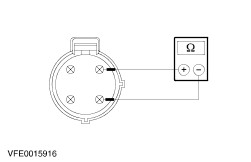
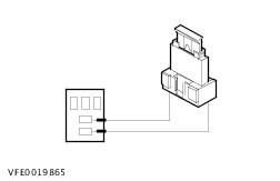
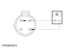
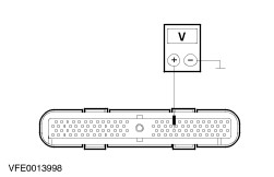
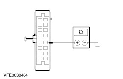
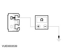
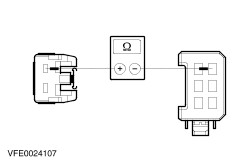
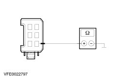
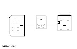
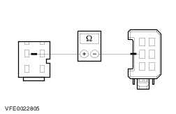
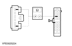
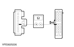
Symptom Chart Symptom Chart | Symptom | Possible Sources | Action | | Air conditioning inoperative (heater blower OK) | * Fuse(s) * Circuit(s). * Refrigerant quantity. * Air conditioning compressor clutch. * Dual pressure switch. * Air conditioning compressor switch. * Air conditioning wide open throttle (WOT) relay. * Air conditioning compressor clutch diode. * PCM * Heater control module. | * | | Heater blower motor partly/completely inoperative | * Fuse(s) * Circuit(s). * Heater blower motor * Heater blower switch. * Heater blower motor variable resistance. | * | | Heater blower motor runs continuously | * Heater blower switch. * Circuit(s). | * | | Faulty operation of the recirculated air flap | * Circuit(s). * Recirculated air flap * Recirculated air flap positioning motor. * Heater control module. | * | System Tests | PINPOINT TEST A : AIR CONDITIONING INOPERATIVE (HEATER BLOWER OK) | | TEST CONDITIONS | DETAILS/RESULTS/ACTIONS | | A1: CHECK THE OPERATION OF THE A/C COMPRESSOR CLUTCH | | | 1 Ignition switch in position III. | | | 2 Switch on the air-conditioning system. | | | 3 Switch on the heater blower. | | | 4 Check operation of the air conditioning compressor clutch. | | | Does the air conditioning compressor clutch operate? Yes CHECK the refrigerant circuit and refrigerant quantity and RECTIFY as necessary. CHECK operation of system. No | | A2: READOUT FDS/WDS TROUBLE CODES | | | 1 Ignition switch in position 0. | | | 2 Run the engine management diagnostic program to read out the trouble codes using FDS/WDS. | | | Is there a trouble code in the air conditioning area? Yes RESOLVE the faults according to the FDS/WDS instructions. CHECK operation of system. No | | A3: CHECK FUSE F58 | | | 1 CHECK Fuse F58 (CJB). | | | Is the fuse OK? Yes No RENEW fuse F58 (7.5 A). If the fuse blows again after switching on the air conditioning, CHECK the air conditioning compressor clutch diode and RENEW as necessary. If the diode is OK, LOCATE and REPAIR the short to ground with the aid of the Wiring Diagrams. CHECK operation of system. | | A4: CHECK THE VOLTAGE AT FUSE F58 | | | 1 Connect Fuse F58 (CJB). | | | 2 Ignition switch in position II. | | | 3 Test voltage between fuse F58 (7.5 A) and ground. | | | Does the meter display battery voltage? Yes No REPAIR the voltage supply to fuse F58 with the aid of the Wiring Diagrams. CHECK operation of system. | | A5: CHECK FUSE F36 | | | 1 Ignition switch in position 0. | | | 2 CHECK Fuse F36 (CJB). | | | Is the fuse OK? Yes No RENEW fuse F36 (7.5 A). If the fuse blows again, LOCATE and REPAIR the short to ground with the aid of the Wiring Diagrams. CHECK the operation of the system. | | A6: CHECK THE VOLTAGE AT FUSE F36 | | | 1 Connect Fuse F36 (CJB). | | | 2 Test voltage between fuse F36 (7.5 A) and ground. | | | Does the meter display battery voltage? Yes No REPAIR the voltage supply to fuse F36 with the aid of the Wiring Diagrams. CHECK operation of system. | | A7: CHECK THE VOLTAGE SUPPLY AT THE A/C SYSTEM WIDE OPEN THROTTLE RELAY (WOT) | | | 1 Disconnect A/C WOT Relay C1011. | | | 2 Ignition switch in position II. | | | 3 Measure the voltage between the A/C WOT relay, socket C1011, pin 3, wiring harness side and ground. | | | Does the meter display battery voltage? Yes No | | A8: CHECK THE VOLTAGE SUPPLY AT THE DUAL PRESSURE SWITCH | | | 1 Ignition switch in position 0. | | | 2 Disconnect Dual pressure switch C882. | | | 3 Ignition switch in position II. | | | 4 Measure the voltage between the dual pressure switch, connector C882, pin 2, circuit 15-FA38 (GN/RD), wiring harness side and ground. | | | Does the meter display battery voltage? Yes No LOCATE and REPAIR the break in the circuit between fuse F58 and the dual pressure switch using the wiring diagrams. CHECK operation of system. | | A9: CHECK THE DUAL PRESSURE SWITCH | | | 1 Ignition switch in position 0. | | | 2 Measure the resistance at the dual pressure switch, connector C882, between pin 2 and pin 4, component side. | | | Is a resistance of less than 2 Ohm registered? Yes LOCATE and RECTIFY the break in the circuit between the dual pressure switch and the A/C WOT relay with the aid of the Wiring Diagrams. CHECK operation of system. No CHECK the air conditioning system pressure and REPAIR as necessary. If the system pressure is correct, RENEW the dual pressure switch. CHECK operation of system. | | A10: CHECK THE VOLTAGE SUPPLY AT THE A/C SYSTEM WIDE OPEN THROTTLE RELAY (WOT) | | | 1 Disconnect A/C WOT Relay C1011. | | | 2 Ignition switch in position II. | | | 3 Measure the voltage between the A/C WOT relay, socket C1011, pin 3, wiring harness side and ground. | | | Does the meter display battery voltage? Yes No LOCATE and RECTIFY the break in the circuit between the A/C WOT relay and fuse F58 with the aid of the Wiring Diagrams. CHECK operation of system. | | A11: CHECK THE VOLTAGE SUPPLY AT THE A/C WOT RELAY | | | 1 Measure the voltage between A/C WOT relay, socket C1011, pin 1, circuit 15-FA11 (GN/YE), wiring harness side and ground. | | | Does the meter display battery voltage? Yes No REPAIR the voltage supply to the A/C WOT relay using the wiring diagrams. CHECK operation of system. | | A12: CHECK THE A/C COMPRESSOR CLUTCH CIRCUIT | | | 1 Ignition switch in position 0. | | | 2 Use a fused bridging cable (7.5 A) at the A/C WOT relay, socket C1011, between pins 3 and 5, wiring harness side. | | | 3 Ignition switch in position II. | | | 4 Check operation of the air conditioning compressor clutch. | | | Does the air conditioning compressor clutch operate? Yes No | | A13: CHECK THE VOLTAGE SUPPLY OF THE A/C COMPRESSOR CLUTCH | | | 1 Ignition switch in position 0. | | | 2 Disconnect A/C compressor clutch C952. | | | 3 Use a fused bridging cable (7.5 A) at the A/C WOT relay, socket C1011, between pins 3 and 5, wiring harness side. | | | 4 Ignition switch in position II. | | | 5 Measure the voltage between the A/C compressor clutch, connector C952, pin 1, circuit 15S-FA6 (GN/YE), wiring harness side and ground. | | | Does the meter display battery voltage? Yes No LOCATE and RECTIFY the break in the circuit between the A/C WOT relay and the air conditioning compressor clutch with the aid of the Wiring Diagrams. CHECK the operation of the system. | | A14: CHECK THE GROUND CONNECTION OF THE A/C COMPRESSOR CLUTCH | | | 1 Ignition switch in position 0. | | | 2 Measure the resistance between the air conditioning compressor clutch, connector C952, pin 2, circuit 31-FA6 (BK), wiring harness side and ground. | | | Is a resistance of less than 2 Ohm registered? Yes RENEW the air conditioning compressor clutch. CHECK the operation of the system. No LOCATE and REPAIR the break in the circuit between the A/C compressor clutch and ground point G56 using the wiring diagrams. CHECK the operation of the system. | | A15: CHECK THE A/C SYSTEM WIDE OPEN THROTTLE RELAY (WOT) | | | 1 Test the A/C WOT relay according to the component tests at the end of this section. | | | Is the A/C WOT relay in order? Yes No RENEW the A/C WOT relay. CHECK the operation of the system. | | A16: CHECK THE VOLTAGE SUPPLY AT THE A/C COMPRESSOR SWITCH | | | 1 Ignition switch in position 0. | | | 2 Disconnect Air conditioning compressor switch C692. | | | 3 Ignition switch in position II. | | | 4 Switch on the air-conditioning system. | | | 5 Switch on the heater blower. | | | 6 Measure the voltage between the air conditioning compressor switch, connector C692, pin 4, circuit 15S-FA17 (GN/OG), wiring harness side and ground. | | | Does the meter display battery voltage? Yes No | | A17: CHECK A/C SYSTEM COMPRESSOR SWITCH | | | 1 Ignition switch in position 0. | | | 2 Measure the resistance at the air conditioning compressor cycling switch connector C692 between pin 4 and pin 1, component side. | | | Is a resistance of less than 2 Ohm registered? Yes Vehicle built before 05/99 with EEC V (60 Pin): GO to A20. Vehicle built before 05/99 with EEC V (104 Pin): GO to A22. No CHECK the refrigerant quantity and CORRECT as necessary. If the refrigerant quantity is correct, RENEW the air conditioning compressor cycling switch. CHECK the operation of the system. | | A18: CHECK THE VOLTAGE SUPPLY AT THE DUAL PRESSURE SWITCH | | | 1 Connect Air conditioning compressor switch C692. | | | 2 Disconnect Dual pressure switch C882. | | | 3 Ignition switch in position II. | | | 4 Switch on the air-conditioning system. | | | 5 Switch on the heater blower. | | | 6 Measure the voltage between the dual pressure switch, connector C882, pin 2, circuit 15S-FA38 (GN/RD), wiring harness side and ground. | | | Does the meter display battery voltage? Yes No LOCATE and REPAIR the break in circuit C between the A/C compressor switch and the dual pressure switch using the wiring diagrams. CHECK the operation of the system. | | A19: CHECK THE DUAL PRESSURE SWITCH | | | 1 Ignition switch in position 0. | | | 2 Measure the resistance at the dual pressure switch, connector C882, between pin 2 and pin 4, component side. | | | Is a resistance of less than 2 Ohm registered? Yes No CHECK the air conditioning system pressure and REPAIR as necessary. If the system pressure is correct, RENEW the dual pressure switch. CHECK the operation of the system. | | A20: CHECK THE VOLTAGE AT THE PCM | | | 1 Connect Dual pressure switch C882. | | | 2 Disconnect PCM C416. | | | 3 Ignition switch in position II. | | | 4 Switch on the air-conditioning system. | | | 5 Switch on the heater blower. | | | 6 Measure the voltage between PCM, connector C416, pin 10, circuit 15S-RE18 (GN/YE), (vehicles built from 05/99): circuit 15S-RE8 (GN/YE), wiring harness side and ground. | | | Does the meter display battery voltage? Yes No LOCATE and REPAIR break in circuit 15S-RE18 (GN/YE) or 15S-RE8 (GN/YE) using the wiring diagrams. CHECK the operation of the system. | | A21: CHECK THE VOLTAGE AT THE PCM | | | 1 Ignition switch in position 0. | | | 2 Connect A/C WOT Relay C1011. | | | 3 Ignition switch in position II. | | | 4 Measure the voltage between the PCM, connector C416, pin 54, circuit 31S-FA11 (BK/YE), wiring harness side and ground. | | | Does the meter display battery voltage? Yes CHECK the PCM and RENEW it if necessary. CHECK the operation of the system. No LOCATE and RECTIFY the break in the circuit between the A/C WOT relay and the PCM with the aid of the Wiring Diagrams. CHECK the operation of the system. | | A22: CHECK THE VOLTAGE AT THE PCM | | | 1 Connect Dual pressure switch C882. | | | 2 Disconnect PCM C415. | | | 3 Ignition switch in position II. | | | 4 Switch on the air-conditioning system. | | | 5 Switch on the heater blower. | | | 6 Measure the voltage between PCM, connector C415, pin 41, circuit 15S-RE18 (GN/YE), (vehicles built from 05/99): circuit 15S-RE8 (GN/YE), wiring harness side and ground. | | | Does the meter display battery voltage? Yes No LOCATE and REPAIR break in circuit 15S-RE18 (GN/YE) or 15S-RE8 (GN/YE) using the wiring diagrams. CHECK the operation of the system. | | A23: CHECK THE VOLTAGE AT THE PCM | | | 1 Ignition switch in position 0. | | | 2 Connect A/C WOT Relay C1011. | | | 3 Ignition switch in position II. | | | 4 Measure the voltage between the PCM, connector C415, pin 69, circuit 31S-FA11 (BK/YE), wiring harness side and ground. | | | Does the meter display battery voltage? Yes CHECK the PCM and RENEW it if necessary. CHECK the operation of the system. No LOCATE and RECTIFY the break in the circuit between the A/C WOT relay and the PCM with the aid of the Wiring Diagrams. CHECK the operation of the system. | | A24: CHECK THE CIRCUIT BETWEEN THE HEATER CONTROL MODULE AND THE A/C COMPRESSOR SWITCH | | | 1 Ignition switch in position 0. | | | 2 Disconnect Heater control module C380. | | | 3 Measure the resistance between the heater control module, connector C380, pin 9, circuit 15S-FA17 (GN/OG), wiring harness side and the A/C compressor switch, connector C692, pin 4, circuit 15S-FA17 (GN/OG), wiring harness side. | | | Is a resistance of less than 2 Ohm registered? Yes No LOCATE and RECTIFY the break in circuit 15S-FA17 (GN/OG) between the heater control module and the A/C compressor switch with the aid of the Wiring Diagrams. CHECK the operation of the system. | | A25: TEST THE VOLTAGE AT THE HEATER CONTROL MODULE | | | 1 Measure the voltage between the heater control module, connector C380, pin 8, circuit 29-FA13 (OG), wiring harness side and ground. | | | Does the meter display battery voltage? Yes No LOCATE and REPAIR the break in the circuit between fuse F36 and the heater control module with the aid of the Wiring Diagrams. CHECK the operation of the system. | | A26: CHECK THE VOLTAGE AT THE HEATER CONTROL MODULE | | | 1 Ignition switch in position II. | | | 2 Measure the voltage between the heater control module, connector C380, pin 10 and ground. | | | Does the meter display battery voltage? Yes No LOCATE and REPAIR the break in the circuit between the heater control module and fuse F58 with the aid of the Wiring Diagrams. CHECK the operation of the system. | | A27: CHECK THE VOLTAGE AT THE HEATER CONTROL MODULE | | | 1 Ignition switch in position III. | | | 2 Measure the voltage between the heater control module, connector C380, pin 11 wiring harness side and ground. | | | Does the meter display battery voltage? Yes No LOCATE AND REPAIR break in circuit between the heater control module and engine run relay using the wiring diagrams. CHECK the operation of the system. | | A28: CHECK THE GROUND CONNECTION OF THE HEATER CONTROL MODULE | | | 1 Ignition switch in position 0. | | | 2 Measure the resistance between the heater control module, connector C380, pin 12, 91-FA13 (BK/OG), wiring harness side and ground. | | | Is a resistance of less than 2 Ohm registered? Yes No LOCATE and REPAIR the break in the circuit between the heater control module and ground point G41 with the aid of the Wiring Diagrams. CHECK the operation of the system. | | A29: CHECK THE CIRCUIT BETWEEN THE HEATER CONTROL MODULE AND THE HEATER BLOWER SWITCH | | | 1 Set the heater blower switch to "slow". | | | 2 Measure the resistance between the heater control module, connector C380, pin 6, circuit 31S-FA26 (BK/RD), wiring harness side and ground. | | | Is a resistance of less than 2 Ohm registered? Yes CHECK and if necessary RENEW the heater control module. CHECK the operation of the system. No LOCATE and RECTIFY the open circuit in circuit 31S-FA26 (BK/RD) between the heater control module and the heater blower switch with the aid of the Wiring Diagrams. CHECK the operation of the system. | | PINPOINT TEST B : HEATER BLOWER MOTOR PARTLY/COMPLETELY INOPERATIVE | | TEST CONDITIONS | DETAILS/RESULTS/ACTIONS | | B1: DETERMINE THE CONDITIONS UNDER WHICH THE FAULT OCCURS | | | 1 Ignition switch in position II. | | | 2 Switch the heater blower switch through all three settings. | | | Is the heater blower motor inoperative in all three switch positions? Yes No | | B2: CHECK FUSE F64 | | | 1 Ignition switch in position 0. | | | 2 CHECK Fuse F64 (BJB). | | | Is the fuse OK? Yes No RENEW fuse F64 (30 A). CHECK system operates correctly If the fuse blows again, LOCATE and REPAIR the short to ground with the aid of the Wiring Diagrams. | | B3: CHECK THE VOLTAGE AT FUSE F64 | | | 1 Connect Fuse F64 (BJB). | | | 2 Ignition switch in position II. | | | 3 Test voltage between fuse F64 (30 A) and ground. | | | Does the meter display battery voltage? Yes No REPAIR the voltage supply to fuse F64 with the aid of the Wiring Diagrams. CHECK system operates correctly | | B4: CHECK THE VOLTAGE AT THE HEATER BLOWER MOTOR | | | 1 Ignition switch in position 0. | | | 2 Disconnect Heater blower motor C789. | | | 3 Ignition switch in position II. | | | 4 Measure the voltage between the heater blower motor, connector C789, pin 1, circuit 15-FA18 (GN/OG), wiring harness side and ground. | | | Does the meter display battery voltage? Yes No LOCATE and REPAIR the break in the circuit between the heater blower motor and fuse F64 with the aid of the Wiring Diagrams. CHECK system operates correctly | | B5: CHECK THE GROUND CONNECTION OF THE HEATER BLOWER MOTOR | | | 1 Ignition switch in position 0. | | | 2 Set the heater blower switch to "maximum". | | | 3 Measure the resistance between the heater blower motor connector C789, pin 2, circuit 31S-FA18 (BK/RD), wiring harness side and ground. | | | Is a resistance of less than 2 Ohm registered? Yes RENEW the heater blower motor. CHECK system operates correctly No | | B6: CHECK THE CIRCUIT BETWEEN THE HEATER BLOWER MOTOR AND THE HEATER BLOWER SWITCH | | | 1 Disconnect Heater blower switch C469. | | | 2 Measure the resistance between the heater blower motor, connector C789, pin 2, circuit 31S-FA18 (BK/RD), wiring harness side and the heater blower switch, connector C469, pin 4, circuit 31S-FA33 (BK/OG), wiring harness side. | | | Is a resistance of less than 2 Ohm registered? Yes No LOCATE and RECTIFY open circuit in circuit 31S-FA18 (BK/RD) between the heater blower motor and soldered connection S24 with the aid of the Wiring Diagrams. CHECK system operates correctly | | B7: CHECK THE GROUND CONNECTION OF THE HEATER BLOWER SWITCH | | | 1 Measure the resistance between the heater blower switch, connector C469, pin 6, circuit 31-FA25 (BK), wiring harness side and ground. | | | Is a resistance of less than 2 Ohm registered? Yes RENEW the heater blower switch. CHECK system operates correctly No LOCATE and REPAIR the break in the circuit between the heater blower switch and ground point G14 using the wiring diagrams. CHECK system operates correctly | | B8: CHECK THE CIRCUIT BETWEEN THE HEATER BLOWER MOTOR AND THE HEATER BLOWER SWITCH | | | 1 Disconnect Heater blower switch C469. | | | 2 Measure the resistance between the heater blower motor, connector C789, pin 2, circuit 31S-FA18 (BK/RD), wiring harness side and the heater blower switch, connector C469, pin 6, circuit 31S-FA33 (BK/OG), wiring harness side. | | | Is a resistance of less than 2 Ohm registered? Yes No LOCATE and RECTIFY open circuit in circuit 31S-FA18 (BK/RD) between the heater blower motor and soldered connection S24 with the aid of the Wiring Diagrams. CHECK system operates correctly | | B9: CHECK THE GROUND CONNECTION OF THE HEATER BLOWER SWITCH | | | 1 Measure the resistance between the heater blower switch, connector C469, pin 2, circuit 31-FA25 (BK), wiring harness side and ground. | | | Is a resistance of less than 2 Ohm registered? Yes RENEW the heater blower switch. CHECK system operates correctly No LOCATE and REPAIR the break in the circuit between the heater blower switch and ground point G14 using the wiring diagrams. CHECK system operates correctly | | B10: DETERMINE THE CONDITIONS UNDER WHICH THE FAULT OCCURS | | | 1 Set the heater blower switch to "maximum". | | | Is the heater blower motor inoperative? Yes No | | B11: CHECK THE CIRCUIT BETWEEN THE HEATER BLOWER MOTOR AND THE HEATER BLOWER SWITCH | | | 1 Ignition switch in position 0. | | | 2 Disconnect Heater blower switch C469. | | | 3 Disconnect Heater blower motor C789. | | | 4 Measure the resistance between the heater blower motor, connector C789, pin 2, circuit 31S-FA18 (BK/RD), wiring harness side and the heater blower switch, connector C469, pin 4, circuit 31S-FA33 (BK/OG), wiring harness side. | | | Is a resistance of less than 2 Ohm registered? Yes RENEW the heater blower switch. CHECK system operates correctly No LOCATE and RECTIFY open circuit in circuit 31S-FA33 (BK/OG) between the heater blower switch and soldered connection S24 with the aid of the Wiring Diagrams. CHECK system operates correctly | | B12: CHECK THE CIRCUIT BETWEEN THE HEATER BLOWER MOTOR AND THE HEATER BLOWER SWITCH | | | 1 Ignition switch in position 0. | | | 2 Disconnect Heater blower switch C469. | | | 3 Disconnect Heater blower motor C789. | | | 4 Measure the resistance between the heater blower motor, connector C789, pin 2, circuit 31S-FA18 (BK/RD), wiring harness side and the heater blower switch, connector C469, pin 6, circuit 31S-FA33 (BK/OG), wiring harness side. | | | Is a resistance of less than 2 Ohm registered? Yes RENEW the heater blower switch. CHECK system operates correctly No LOCATE and RECTIFY open circuit in circuit 31S-FA33 (BK/OG) between the heater blower switch and soldered connection S24 with the aid of the Wiring Diagrams. CHECK system operates correctly | | B13: CHECK THE HEATER BLOWER SWITCH | | | 1 Ignition switch in position 0. | | | 2 Disconnect Heater blower switch C469. | | | 3 Ignition switch in position II. | | | 4 Measure the voltage between the heater blower switch, connector C469, pin 1, circuit 31S-FA32 (BK/BU), wiring harness side and ground. | | | 5 Measure the voltage between the heater blower switch, connector C469, pin 2, circuit 31S-FA31 (BK/YE), wiring harness side and ground. | | | 6 Measure the voltage between the heater blower switch, connector C469, pin 3, circuit 31S-FA30 (BK/WH), wiring harness side and ground. | | | Do all measurements show battery voltage? Yes RENEW the heater blower switch. CHECK system operates correctly No | | B14: CHECK THE CIRCUIT BETWEEN THE HEATER BLOWER MOTOR AND THE VARIABLE HEATER BLOWER RESISTOR. | | | 1 Ignition switch in position 0. | | | 2 Disconnect Heater blower variable resistor C470. | | | 3 Ignition switch in position II. | | | 4 Measure the voltage between the heater blower motor variable resistor, connector C470, pin 1, circuit 31S-FA1 (BK/BU), wiring harness side and ground. | | | Does the meter display battery voltage? Yes No LOCATE and RECTIFY break in circuit 31S-FA1 (BK/BU) between the heater blower variable resistor and soldered connection S24 with the aid of the Wiring Diagrams. CHECK system operates correctly | | B15: CHECK THE CIRCUIT BETWEEN THE HEATER BLOWER VARIABLE RESISTOR AND THE HEATER BLOWER SWITCH | | | 1 Ignition switch in position 0. | | | 2 Measure the resistance between the heater blower motor variable resistor, connector C470, pin 4, circuit 31S-FA32 (BK/BU), wiring harness side and the heater blower switch, connector C469, pin 1, circuit 31S-FA32 (BK/BU), wiring harness side. | | | Is a resistance of less than 2 Ohm registered? Yes No LOCATE and RECTIFY the open circuit in circuit 31S-FA32 (BK/BU) between the heater blower motor variable resistor and the heater blower switch with the aid of the Wiring Diagrams. CHECK system operates correctly | | B16: CHECK THE CIRCUIT BETWEEN THE HEATER BLOWER VARIABLE RESISTOR AND THE HEATER BLOWER SWITCH | | | 1 Measure the resistance between the heater blower motor variable resistor, connector C470, pin 2, circuit 31S-FA31 (BK/YE), wiring harness side and the heater blower switch, connector C469, pin 2, circuit 31S-FA31 (BK/YE), wiring harness side. | | | Is a resistance of less than 2 Ohm registered? Yes No LOCATE and RECTIFY the open circuit in circuit 31S-FA31 (BK/YE) between the heater blower motor variable resistor and the heater blower switch with the aid of the Wiring Diagrams. CHECK system operates correctly | | B17: CHECK THE CIRCUIT BETWEEN THE HEATER BLOWER VARIABLE RESISTOR AND THE HEATER BLOWER SWITCH | | | 1 Measure the resistance between the heater blower motor variable resistor, connector C470, pin 3, circuit 31S-FA30 (BK/WH), wiring harness side and the heater blower switch, connector C469, pin 3, circuit 31S-FA30 (BK/WH), wiring harness side. | | | Is a resistance of less than 2 Ohm registered? Yes RENEW the heater blower motor variable resistor. CHECK system operates correctly No LOCATE and RECTIFY the open circuit in circuit 31S-FA30 (BK/YE) between the heater blower motor variable resistor and the heater blower switch with the aid of the Wiring Diagrams. CHECK system operates correctly | | B18: CHECK THE HEATER BLOWER SWITCH | | | 1 Ignition switch in position 0. | | | 2 Disconnect Heater blower switch C469. | | | 3 Ignition switch in position II. | | | 4 Measure the voltage between the heater blower switch, connector C469, pin 5, circuit 31S-FA32 (BK/BU), wiring harness side and ground. | | | 5 Measure the voltage between the heater blower switch, connector C469, pin 3, circuit 31S-FA31 (BK/YE), wiring harness side and ground. | | | 6 Measure the voltage between the heater blower switch, connector C469, pin 1, circuit 31S-FA30 (BK/WH), wiring harness side and ground. | | | Do all measurements show battery voltage? Yes RENEW the heater blower switch. CHECK system operates correctly No | | B19: CHECK THE CIRCUIT BETWEEN THE HEATER BLOWER MOTOR AND THE VARIABLE HEATER BLOWER RESISTOR. | | | 1 Ignition switch in position 0. | | | 2 Disconnect Heater blower variable resistor C470. | | | 3 Ignition switch in position II. | | | 4 Measure the voltage between the heater blower motor variable resistor, connector C470, pin 1, circuit 31S-FA1 (BK/BU) (from 08/2000 circuit 31S-FA33 (BK/OG)), wiring harness side and ground. | | | Does the meter display battery voltage? Yes No LOCATE and RECTIFY the break in the circuit between solder point S24 and the heater blower variable resistor with the aid of the Wiring Diagrams. CHECK system operates correctly | | B20: CHECK THE CIRCUIT BETWEEN THE HEATER BLOWER VARIABLE RESISTOR AND THE HEATER BLOWER SWITCH | | | 1 Ignition switch in position 0. | | | 2 Measure the resistance between the heater blower motor variable resistor, connector C470, pin 4, circuit 31S-FA32 (BK/BU), wiring harness side and the heater blower switch, connector C469, pin 5, circuit 31S-FA32 (BK/BU), wiring harness side. | | | Is a resistance of less than 2 Ohm registered? Yes No LOCATE and RECTIFY the open circuit in circuit 31S-FA32 (BK/BU) between the heater blower motor variable resistor and the heater blower switch with the aid of the Wiring Diagrams. CHECK system operates correctly | | B21: CHECK THE CIRCUIT BETWEEN THE HEATER BLOWER VARIABLE RESISTOR AND THE HEATER BLOWER SWITCH | | | 1 Measure the resistance between the heater blower motor variable resistor, connector C470, pin 3, circuit 31S-FA31 (BK/YE), wiring harness side and the heater blower switch, connector C469, pin 2, circuit 31S-FA31 (BK/YE), wiring harness side. | | | Is a resistance of less than 2 Ohm registered? Yes No LOCATE and RECTIFY the open circuit in circuit 31S-FA31 (BK/YE) between the heater blower motor variable resistor and the heater blower switch with the aid of the Wiring Diagrams. CHECK system operates correctly | | B22: CHECK THE CIRCUIT BETWEEN THE HEATER BLOWER VARIABLE RESISTOR AND THE HEATER BLOWER SWITCH | | | 1 Measure the resistance between the heater blower motor variable resistor, connector C470, pin 1, circuit 31S-FA30 (BK/WH), wiring harness side and the heater blower switch, connector C469, pin 3, circuit 31S-FA30 (BK/WH), wiring harness side. | | | Is a resistance of less than 2 Ohm registered? Yes RENEW the heater blower motor variable resistor. CHECK system operates correctly No LOCATE and RECTIFY the open circuit in circuit 31S-FA30 (BK/YE) between the heater blower motor variable resistor and the heater blower switch with the aid of the Wiring Diagrams. CHECK system operates correctly | | PINPOINT TEST C : BLOWER MOTOR RUNS CONTINUOUSLY | | TEST CONDITIONS | DETAILS/RESULTS/ACTIONS | | C1: CHECK THE HEATER BLOWER SWITCH | | | 1 Ignition switch in position 0. | | | 2 Disconnect Heater blower switch C469. | | | 3 Ignition switch in position II. | | | 4 Check operation of the heater blower motor. | | | Does the heater blower motor run continuously? Yes No RENEW the heater blower switch. CHECK system operates correctly | | C2: CHECK THE CIRCUIT AT THE HEATER BLOWER VARIABLE RESISTOR | | | 1 Ignition switch in position 0. | | | 2 Disconnect Heater blower variable resistor C470. | | | 3 Ignition switch in position II. | | | 4 Check operation of the heater blower motor. | | | Does the heater blower motor run continuously? Yes CHECK for short to ground in all circuits that are connected to solder point S24 using the wiring diagrams and REPAIR. CHECK system operates correctly No CHECK for short to ground in all circuits between the heater blower variable resistor and the heater blower switch using the wiring diagrams and REPAIR. CHECK system operates correctly | | PINPOINT TEST D : FAULTY OPERATION OF THE RECIRCULATED AIR FLAP | | TEST CONDITIONS | DETAILS/RESULTS/ACTIONS | | D1: DETERMINE THE MODEL VARIANT | | | 1 Determine the model variant. | | | Was the vehicle built before 05/99? Yes No | | D2: CHECK THE GROUND CONNECTION OF THE RECIRCULATED AIR FLAP POSITIONING MOTOR | | | 1 Ignition switch in position 0. | | | 2 Disconnect Recirculated air flap positioning motor C375. | | | 3 Measure resistance between recirculated air flap positioning motor, connector C375, pin 4, wiring harness side and ground. | | | Is a resistance of less than 2 Ohm registered? Yes No LOCATE and REPAIR the break in the circuit between the recirculated air flap positioning motor and ground point G41 with the aid of the Wiring Diagrams. CHECK system operates correctly | | D3: CHECK THE CIRCUIT BETWEEN THE HEATER CONTROL MODULE AND THE RECIRCULATED AIR FLAP POSITIONING MOTOR | | | 1 Disconnect Heater control module C380. | | | 2 Measure the resistance between the heater control module, connector C380, pin 16, circuit 33-FA76 (YE/BU), wiring harness side and the recirculated air flap positioning motor, connector C375, pin 1, circuit 33-FA76 (YE/BU) (right-hand drive vehicle: pin 6, circuit 32-FA76 (WH/BU)), wiring harness side. | | | Is a resistance of less than 2 Ohm registered? Yes No LOCATE and RECTIFY the break in circuit 33-FA76 (YE/BU) or circuit 32-FA76 (WH/BU) between the heater control module and the recirculated air flap positioning motor with the aid of the Wiring Diagrams. CHECK system operates correctly | | D4: CHECK THE CIRCUIT BETWEEN THE HEATER CONTROL MODULE AND THE RECIRCULATED AIR FLAP POSITIONING MOTOR | | | 1 Measure the resistance between the heater control module, connector C380, pin 14, circuit 32-FA76 (WH/BU), wiring harness side and the recirculated air flap positioning motor, connector C375, pin 6, circuit 32-FA76 (WH/BU) (right-hand drive vehicle: pin 1, circuit 33-FA76 (YE/BU)), wiring harness side. | | | Is a resistance of less than 2 Ohm registered? Yes No LOCATE and RECTIFY the break in circuit 32-FA76 (WH/BU) or circuit 33-FA76 (YE/BU) between the heater control module and the recirculated air flap positioning motor with the aid of the Wiring Diagrams. CHECK system operates correctly | | D5: CHECK THE CIRCUIT BETWEEN THE RECIRCULATED AIR FLAP POSITIONING MOTOR AND THE HEATER CONTROL MODULE | | | 1 Measure the resistance between the heater control module, connector C380, pin 4, circuit 91S-FA90 (BK/GN), wiring harness side and the recirculated air flap positioning motor, connector C375, pin 3, circuit 91S-FA90 (BK/GN), wiring harness side. | | | Is a resistance of less than 2 Ohm registered? Yes No LOCATE and RECTIFY the open circuit in circuit 91S-FA90 (BK/GN) between the heater control module and the recirculated air flap positioning motor with the aid of the Wiring Diagrams. CHECK system operates correctly | | D6: CHECK HEATER CONTROL MODULE | NOTE:The recirculated air function cannot be activated if the air distribution control is set to "Defrost windscreen/keep windscreen demisted". | | | 1 Connect Heater control module C380. | | | 2 Ignition switch in position II. | | | 3 Switch on recirculated air function. | | | 4 Measure the voltage at the recirculated air flap positioning motor, connector C375, between pin 1 and pin 6, wiring harness side. | | | Is a voltage of at least 10 Volts registered? Yes No CHECK and if necessary RENEW the heater control module. CHECK system operates correctly | | D7: CHECK HEATER CONTROL MODULE | | | 1 Switch off recirculated air function. | | | 2 Measure the voltage again at the recirculated air flap positioning motor, connector C375, between pin 1 and pin 6, wiring harness side. | | | Has the polarity of the voltage changed? Yes CHECK that the recirculated air flap moves freely. If the recirculated air flap is mechanically OK, RENEW the recirculated air flap positioning motor. CHECK system operates correctly No CHECK and if necessary RENEW the heater control module. CHECK system operates correctly | | D8: CHECK THE GROUND CONNECTION OF THE RECIRCULATED AIR FLAP POSITIONING MOTOR | | | 1 Ignition switch in position 0. | | | 2 Disconnect Recirculated air flap positioning motor C375. | | | 3 Measure resistance between recirculated air flap positioning motor, connector C375, pin 3, wiring harness side and ground. | | | Is a resistance of less than 2 Ohm registered? Yes No LOCATE and REPAIR the break in the circuit between the recirculated air flap positioning motor and ground point G41 with the aid of the Wiring Diagrams. CHECK system operates correctly | | D9: CHECK THE CIRCUIT BETWEEN THE HEATER CONTROL MODULE AND THE RECIRCULATED AIR FLAP POSITIONING MOTOR | | | 1 Disconnect Heater control module C380. | | | 2 Measure the resistance between the heater control module, connector C380, pin 16, circuit 33-FA76 (YE/BU), wiring harness side and the recirculated air flap positioning motor, connector C375, pin 6, circuit 33-FA76 (YE/BU) (right-hand drive vehicle: pin 1, circuit 32-FA76 (WH/BU)), wiring harness side. | | | Is a resistance of less than 2 Ohm registered? Yes No LOCATE and RECTIFY the break in circuit 33-FA76 (YE/BU) or circuit 32-FA76 (WH/BU) between the heater control module and the recirculated air flap positioning motor with the aid of the Wiring Diagrams. CHECK system operates correctly | | D10: CHECK THE CIRCUIT BETWEEN THE HEATER CONTROL MODULE AND THE RECIRCULATED AIR FLAP POSITIONING MOTOR | | | 1 Measure the resistance between the heater control module, connector C380, pin 14, circuit 32-FA76 (WH/BU), wiring harness side and the recirculated air flap positioning motor, connector C375, pin 1, circuit 32-FA76 (WH/BU) (right-hand drive vehicle: pin 6, circuit 33-FA76 (YE/BU)), wiring harness side. | | | Is a resistance of less than 2 Ohm registered? Yes No LOCATE and RECTIFY the break in circuit 32-FA76 (WH/BU) or circuit 33-FA76 (YE/BU) between the heater control module and the recirculated air flap positioning motor with the aid of the Wiring Diagrams. CHECK system operates correctly | | D11: CHECK THE CIRCUIT BETWEEN THE RECIRCULATED AIR FLAP POSITIONING MOTOR AND THE HEATER CONTROL MODULE | | | 1 Measure the resistance between the recirculated air flap positioning motor, connector C375, pin 4, circuit 91S-FA90 (BK/GN), wiring harness side and the heater control module, connector C380, pin 4, circuit 91S-FA90 (BK/GN), wiring harness side. | | | Is a resistance of less than 2 Ohm registered? Yes No LOCATE and RECTIFY the open circuit in circuit 91S-FA90 (BK/GN) between the heater control module and the recirculated air flap positioning motor with the aid of the Wiring Diagrams. CHECK system operates correctly | | D12: CHECK HEATER CONTROL MODULE | NOTE:The recirculated air function cannot be activated if the air distribution control is set to "Defrost windscreen/keep windscreen demisted". | | | 1 Connect Heater control module C380. | | | 2 Ignition switch in position II. | | | 3 Switch on recirculated air function. | | | 4 Measure the voltage at the recirculated air flap positioning motor, connector C375, between pin 1 and pin 6, wiring harness side. | | | Is a voltage of at least 10 Volts registered? Yes No CHECK and if necessary RENEW the heater control module. CHECK system operates correctly | | D13: CHECK HEATER CONTROL MODULE | | | 1 Switch off recirculated air function. | | | 2 Measure the voltage again at the recirculated air flap positioning motor, connector C375, between pin 1 and pin 6, wiring harness side. | | | Has the polarity of the voltage changed? Yes CHECK that the recirculated air flap moves freely. If the recirculated air flap is mechanically OK, RENEW the recirculated air flap positioning motor. CHECK system operates correctly No CHECK and if necessary RENEW the heater control module. CHECK system operates correctly | Component Tests Air conditioning wide open throttle (WOT) relay. - Check the normally open contact in the unswitched state.
- Measure the resistance at the relay, between pin 3 and pin 5, component side.
- Is a resistance of more than 10 kOhms registered? If yes, go to 2. If no, RENEW the relay.
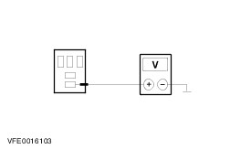
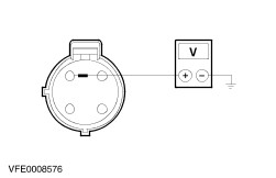
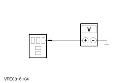
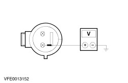
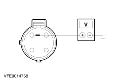
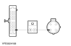
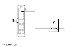
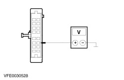
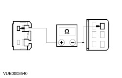
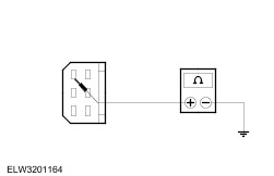
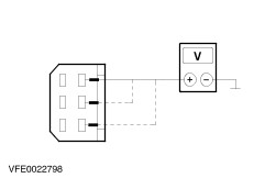
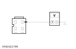
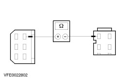
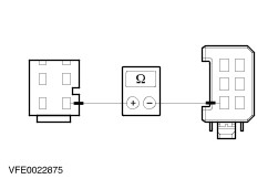
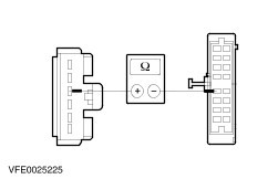
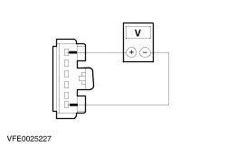
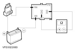
- Check the normally open contact in the switched state.
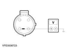
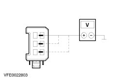
- Using a fused test cable (1 A), connect pin 1 of the relay, component side, with the battery positive pole.
- Using a test cable, connect pin 2 of the relay, component side, with the battery negative pole.
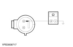
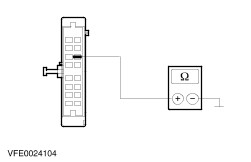
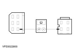
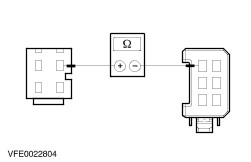
- Measure the resistance at the relay, between pin 3 and pin 5, component side.
- Is a resistance of less than 2 Ohm registered? If yes, the relay is OK. If no, RENEW relay.
|