| PINPOINT TEST A : GENERIC ELECTRONIC MODULE (GEM) NOT COMMUNICATING WITH THE DIAGNOSTIC UNIT |
| TEST CONDITIONS | DETAILS/RESULTS/ACTIONS |
| A1: CHECK FUSE F31 |
| | 1 CHECK fuse F31 (CJB). |
| | Is the fuse OK? Yes No RENEW fuse F31 (3 A). CHECK the operation of the system. If the fuse blows again, LOCATE and REPAIR the short to ground using the Wiring Diagrams. |
| A2: CHECK THE VOLTAGE AT FUSE F31 |
| | 1 Connect fuse F31 (CJB). |
| | 2 Ignition switch in position I. |
| | 3 Measure the voltage between fuse F31 (3 A) and ground. |
| | Does the meter display battery voltage? Yes No REPAIR the voltage supply to fuse F31 using the Wiring Diagrams. CHECK the operation of the system. |
| A3: CHECK FUSE F3 |
| | 1 Ignition switch in position 0. |
| | 2 CHECK fuse F3 (CJB). |
| | Is the fuse OK? Yes No RENEW fuse F3 (5 A). CHECK the operation of the system. If the fuse blows again, LOCATE and REPAIR the short to ground using the Wiring Diagrams. |
| A4: CHECK THE VOLTAGE AT FUSE F3 |
| | 1 Connect fuse F3 (CJB). |
| | 2 Ignition switch in position II. |
| | 3 Measure the voltage between fuse F3 (5 A) and ground. |
| | Does the meter display battery voltage? Yes No REPAIR the voltage supply to fuse F3 using the Wiring Diagrams. CHECK the operation of the system. |
| A5: CHECK THE VOLTAGE AT THE GENERIC ELECTRONIC MODULE (GEM) |
| | 1 Ignition switch in position 0. |
| | 2 Disconnect GEM C1. |
| | 3 Ignition switch in position I. |
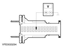
| | 4 Measure the voltage between the GEM, connector C1, pin 19 (BN/WH), wiring harness side and ground. |
| | Does the meter display battery voltage? Yes No LOCATE and REPAIR the break in the circuit between the GEM and fuse F31 with the aid of the Wiring Diagrams. CHECK the operation of the system. |
| A6: CHECK THE VOLTAGE AT THE GEM |
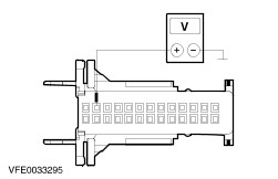
| | 1 Ignition switch in position II. |
| | 2 Measure the voltage between the GEM, connector C1, pin 2 (BK), wiring harness side and ground. |
| | Does the meter display battery voltage? Yes No LOCATE and REPAIR the break in the circuit between the GEM and soldered connection S3 using the Wiring Diagrams. CHECK the operation of the system. |
| A7: CHECK THE VOLTAGE AT THE GEM |
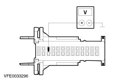
| | 1 Measure the voltage between the GEM, connector C1, pin 16 (BK/YE), wiring harness side and ground. |
| | Does the meter display battery voltage? Yes No LOCATE and REPAIR the break in the circuit between the GEM and soldered connection S8 using the Wiring Diagrams. CHECK the operation of the system. |
| A8: CHECK THE GEM GROUND CONNECTION |
| | 1 Ignition switch in position 0. |
| | 2 Disconnect GEM C7. |
| | 3 Disconnect GEM C4. |
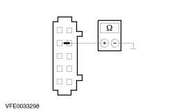
| | 4 Measure the resistance between the GEM, connector C7, pin 3 (BN), wiring harness side and ground. |
| | 5 Measure the resistance between the GEM, connector C4, pin 4 (BN), wiring harness side and ground. |
| | Is a resistance of less than 2 Ohms measured in both cases? Yes No One measurement is greater than 2 Ohms: LOCATE and REPAIR the break in the circuit between the GEM and soldered connection S30 using the Wiring Diagrams. CHECK the operation of the system. Both measurements are greater than 2 Ohms: LOCATE and REPAIR the break in the relevant circuit between soldered connection S30 and ground connection G100 using the Wiring Diagrams. CHECK the operation of the system. |
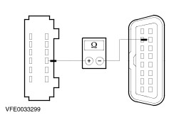
| A9: CHECK FOR OPEN CIRCUIT BETWEEN THE GEM AND THE DATA LINK CONNECTOR (DLC) |
| | 1 Disconnect GEM C3. |
| | 2 Measure the resistance between the GEM, connector C3, pin 7 (GY/WH), wiring harness side and the DLC, connector C199, pin 7 (GY/WH), wiring harness side. |
| | Is a resistance of less than 2 Ohms registered? Yes CHECK the GEM and RENEW as necessary. CHECK the operation of the system. No LOCATE and REPAIR the break in the relevant circuit between the GEM and soldered connection S6 using the Wiring Diagrams. CHECK the operation of the system. |