| Symptom | Possible Sources | Action |
| Loss of oil | * Use of the wrong type of engine oil. | * Establish what oil was last used in the engine (refer to the last bill or oil label), compare it with the specification and change it if necessary. |
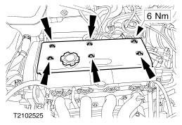
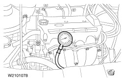
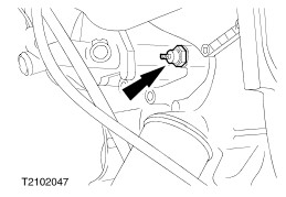
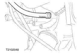
| * Pressure in the cylinder block too high - Faulty crankcase ventilation system - Poor sealing between combustion chamber and crankcase | * Unscrew and remove the oil filler cap. Close off the opening by hand. If pressure can be felt when the engine is running: - Check that the crankcase ventilation system works correctly, repair it if necessary. - Screw the compressed air supply connector into each cylinder in turn, apply the compressed air and observe how the air escapes when the oil filler cap is removed. If there is a noticeable current of air, check the cylinder bores and pistons for damage and measure them. |
| * Leak at a rotating shaft caused by a faulty oil seal or incorrect alignment of the oil seal carrier - Camshaft - Crankshaft front - Crankshaft rear | * Check the alignment of the seal carrier and correct as necessary. Renew the oil seal if necessary. |
| * Damaged gaskets or mating faces - Cylinder head gasket or mating face is damaged, engine oil can escape from the engine between cylinder head and cylinder block or get into the cooling system. | * Check gaskets and mating faces for damage. - Open the coolant reservoir and check whether oil emulsion or a film of oil is visible on the coolant surface. - Remove the cylinder head. Check the mating faces, cylinder head gasket and evenness. Renew the cylinder head if necessary. |
| * Leaks from engine or ancillary components with oilways or which are supplied with an oil film. | * Locate cracks in ancillary components with oilways or in the engine itself by using a UV leak tester, and renew the affected component or gasket. |
| Oil consumption | * Use of the wrong type of engine oil. | * Establish which engine oil was last used (e.g. by referring to the last bill or oil change label) and compare it with the specification. Change the engine oil if necessary. |
| * Faulty crankcase ventilation system. - Hoses or ventilation/breather valve are blocked. This causes excessive pressure in the crankcase which causes more oil to enter the combustion chamber. - The crankcase ventilation system oil thrower is faulty and engine oil can reach the combustion chamber via the inlet manifold. | * Check that the crankcase ventilation system works correctly, repair it if necessary. |
| * Damaged cylinder liners or too much clearance on engine components. - Pistons - Piston rings (clearance in groove and end gap) - Cylinder liners - Valve stems and guides. | * Check the running surfaces and clearances of each individual engine component and renew as necessary. - Pistons - Piston rings - Cylinder liners - Valve stems and guides |
| * Damaged gaskets or mating faces - Cylinder head gasket or mating face is damaged, and engine oil can enter the combustion chamber. - Valve stem oil seals are damaged and engine oil can enter the combustion chamber between valve stem and valve guide. This becomes particularly apparent on overrun. | * Check gaskets and mating faces for damage. - Remove the cylinder head. Check the mating faces, cylinder head gasket and evenness. Renew the cylinder head if necessary. - Renew the valve stem oil seals. |
| * Cracks in engine components with oilways or engine components coated in oil, e.g. cylinder liners, pistons and oil galleries and passages. | * Add UV testing additive to the engine oil and run the engine until the oil temperature is at least 80°C, so that the additive can penetrate into any cracks that are present. Allow the engine to cool to ambient temperature, remove the affected component and disassemble it as necessary. Check the engine component using UV leak detection and renew as necessary. |
| Coolant consumption | * Damaged gaskets or mating faces - The cylinder head gasket or mating face is damaged. Coolant can enter the combustion chamber or the crankcase. | * Check the gaskets and mating faces for damage. - Remove the cylinder head. Check the mating faces, cylinder head gasket and evenness. Renew the cylinder head if necessary. |
| * Cracks or fractures in engine components surrounded by coolant, such as cylinder liners and cylinder head combustion chamber recesses. | * Identify the damaged engine component and renew it. |
| Engine will not start | * Battery or wiring is faulty. | * |
| * Starter motor or wiring is faulty | * |
| * Fuel system is faulty. - Fuel tank is empty. | * Check the fuel system - - Check the fuel level. |
| * Ignition system is faulty. | * |
| * Engine management system is faulty. | * |
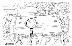
| * Intake system is faulty - Leaking intake system - Air cleaner is blocked - Idle air control valve faulty. | * - Carry out a test of the intake vacuum system. |
| * Valve train is damaged - Burned out exhaust valve - Timing incorrectly adjusted - Toothed belt ripped or damaged. | * Connect compressed air to the cylinders. If air flows out through the intake manifold or the exhaust pipe, check the valve train. Renew the toothed belt. |
| * Engine components faulty - Burned out piston - Piston rings - Cylinder head gasket - Big-end and/or main bearing journals | * Connect compressed air to the cylinders. If air escapes with the cylinder head cover blanking plug open, disassemble the engine as described in the manual and check the components. |
| Low power / fuel consumption too high / rough engine running | * Fuel system faulty | * |
| * Ignition system faulty. | * |
| * Engine management system is faulty. | * |
| * Intake system is faulty - Leaking intake system - Air cleaner is blocked - Idle air control valve is faulty. | * - Carry out a vacuum test on the intake system. |
| * Valve train damaged - Burned out exhaust valve - Timing incorrectly adjusted - Toothed belt ripped or damaged. | * Connect compressed air to the cylinders. If air escapes from the intake manifold or the exhaust pipe, check the valve train. Renew the toothed belt. |
| * Faulty engine components - Piston burned out - Piston rings - Cylinder head gasket - Big-end and/or main bearing journal | * Connect compressed air to the cylinders. If air flows out when the cylinder head cover cap is open, dismantle the engine and check the components. |
| * Variable camshaft timing (VCT) faulty. | * Check the inlet camshaft toothed pulley wheel with VCT unit and the VCT solenoid valve for damage or oil leaks. |
| Noise development | * Misfiring/backfiring - Fuel tank contains the wrong type of fuel or fuel with the incorrect octane rating. - Ignition system is faulty - Engine temperature too high - Carbon deposits in the combustion chamber start to glow and cause misfiring - Timing incorrectly adjusted, which causes misfiring in the intake/exhaust system. | * Determine the cause for the misfiring and rectify it. - Determine which type of fuel was last put in the tank (note the country specific fuel specifications). - - - Remove the carbon deposits by using fuel additives and driving more carefully - Check the valve timings. |
| * Valve train damaged - Valve clearances too great, because of faulty bucket tappets or because they are set incorrectly. - Valve timing incorrectly adjusted - valves and pistons are touching. - Toothed belt ripped or damaged. - Timing belt is too loose (rattling or rubbing noises) or too tight (whistling or humming noises) | * Check the valve train - Adjust the valve clearances and/or renew faulty bucket tappets as necessary. - Check the valve timing and adjust it if necessary. - Check the toothed belt, pistons and valves for damage and renew all damaged components. - Check the toothed belt tension and correct it if necessary. |
| * Engine components faulty - Pistons - Piston rings - Cylinder head gasket - Big-end and/or main bearing journals. | * Disassemble the engine and check components. |
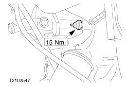
| * Engine ancillary components broken or have come loose. | * Check that the ancillary components are fitted correctly and firmly and tighten them to the specified torque if necessary. |